

Device Lab 2
MRI
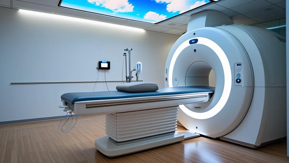
A horizontal-bore superconducting scanner. A persistent main field, three gradient axes and radiofrequency coils work together to acquire signals. The console controls a sequence; it does not photograph the patient directly.
Also called: Magnetic Resonance Imaging, Mr Scanner, Mri Scanner. Arabic: التصوير بالرنين المغناطيسي. Device Lab 2 of 69 in BMEssentia Medical City, 3 configurations.
Overview: the configurations
1.5 T superconducting MRI
A horizontal-bore superconducting scanner. A persistent main field, three gradient axes and radiofrequency coils work together to acquire signals. The console controls a sequence; it does not photograph the patient directly.
3 T superconducting MRI
A higher-field horizontal-bore scanner with a superconducting magnet, gradient insert and radiofrequency chain tuned for its field. More available signal can support a different resolution or time trade-off; it is not a universal promise of a better examination.
Open permanent-magnet MRI
3 T permanent-magnet system with two opposing pole faces and a vertical main field. The patient lies in an open gap. Planar gradients and a compatible radiofrequency coil still encode and receive the signal.
How it works: the main parts
What each part does, from the MRI lessons in the 3D Device Lab.
- Main magnet
- The magnet establishes the steady field around which the rest of MRI is organised. It changes the balance and behaviour of nuclear magnetisation; it does not emit the image.
- Shim system
- Shimming improves how uniform the main field is over the region being examined. If different places experience unintended frequency differences, signal and geometry can suffer.
- Gradient coil assembly
- Gradients deliberately make resonance depend on position. That gives a received signal a spatial address.
- Radiofrequency transmit structure
- A brief radiofrequency field tips the net magnetisation away from equilibrium. That prepares a measurable transverse signal.
- Local receive coil
- The coil close to the anatomy detects a small changing electromagnetic signal. Placement matters: a technically impressive scanner still needs a suitable receiving path near the region of interest.
- Coil connection interface
- This is the boundary between a removable patient-side coil and the scanner receiving system. Correct mechanical engagement does not automatically prove the electrical channels are intact.
- Patient table and drive
- The table positions the anatomy in the intended imaging region. Its indicated coordinate is useful only when the patient, coil and landmark agree with it.
- Positioning controls and landmark
- A landmark connects the physical patient position to the planned scan volume. The operator uses the prescribed positioning method rather than guessing from the shell opening.
Explore it in the Device Lab
- From alignment to excitation: Begin with the steady field. The net magnetisation has a longitudinal component. A controlled radiofrequency pulse changes its direction; the transverse component can contribute to a received signal.
- Give the signal a spatial address: A received waveform mixes contributions from many places. Gradient fields let the system distinguish position through controlled frequency and phase changes. Slice selection also involves an appropriately designed radiofrequency pulse.
- Make contrast a deliberate choice: The same phantom can look different under different sequence weightings. Tissue-related relaxation, timing and readout choices affect signal. Select each weighting and compare regions rather than judging the whole image as simply better or worse.
- Separate motion from RF interference: A technical image problem has a pattern and a context. Motion can create displacement or ghosts; unwanted radiofrequency energy can create structured interference. Turn on one teaching disturbance at a time and compare with baseline.
Common faults and what to check
Guided fault cases in the Device Lab
- The missing receive channel: The coil is not fully recognised. What happens next?
- The image that will not hold still: The patient reports discomfort during acquisition. What is the next priority?
- The stripe that survives a repeat: The pattern persists with a stationary phantom. Which comparison is useful?
- Acquisition stops, the magnet remains: The stop has interrupted scanning. Which statement is safe?
Training cases written by BMEssentia for teaching.
Most reported device problems (FDA MAUDE)
| Device problem | Reports |
|---|---|
| Detachment of Device or Device Component | 1,443 |
| Device Operates Differently Than Expected | 154 |
| Overheating of Device | 66 |
| Fire | 50 |
| Magnetic interference | 49 |
| Device Handling Problem | 48 |
Raw counts of adverse event reports for this device type (FDA product code LNH, MOS), all years. Not adjusted for the number of units in use, so they show what gets reported, not failure rates. Report text is never copied.
Planned maintenance checks
From the BMEssentia procedure library: every 12 months, about 240 minutes, electrical class I, applied part type BF.
The magnet, RF chain and gradients are serviced by the manufacturer under contract. These are the clinical engineering checks around that work.
| Check | Pass when |
|---|---|
| Zone IV, quench pipe and room Walk Zone IV with non-ferromagnetic tools only. Check the quench pipe outlet outside is unobstructed and its exclusion area intact, the RF door fingers and seals, the patient table, coils and cables. | No damage to coils or cables; RF door fingers continuous; quench outlet clear. |
| Helium, cold head and chiller Read the helium level, the cold head and compressor status and the chiller water temperature from the service monitor; compare with last month. | Within the manufacturer's limits; any downward trend reported. |
| Electrical safety of the patient equipment Test the MR-conditional patient monitor, injector and ancillary equipment that is not part of the magnet system to IEC 62353. | IEC 62353: PE ≤ 0.30 Ω; equipment leakage ≤ 500 µA (Class I); applied part BF ≤ 5000 µA. |
| ACR phantom image quality Scan the ACR phantom with the ACR protocol and read geometric accuracy, slice thickness, high-contrast resolution and uniformity. | ACR criteria (see limits); compare SNR with the acceptance baseline. |
| Oxygen monitor and emergency controls Expose the room oxygen sensor to test gas and confirm the alarm. Confirm the emergency stop and the quench button covers are intact and labelled (never press the quench button). | Oxygen alarm at its set limit; controls labelled and guarded. |
| Records Check the manufacturer's PM report, the service log and the safety signage review are filed. | PM report present and signed; open faults have an owner. |
Test instruments: ACR large MRI phantom (or the manufacturer's QA phantom); Non-ferromagnetic hand tools; Electrical safety analyser; Oxygen monitor test gas.
Standards engineers test against
IEC 60601-2-33: MR equipment for medical diagnosis
The particular standard for MRI systems.
Recent FDA recalls
| Recall | Product and reason |
|---|---|
| Z-3307-2026 2026-09-25 | Philips North America: Ingenia Blue Seal SE and Blue Seal XE When exporting diffusion tensor imaging (DTI) scans from a MR system using the Enhanced MR DICOM format, the exports contain incorrect data (diffusion directions). Root cause: Software design. |
| Z-3308-2026 2026-09-25 | Philips North America: Ingenia 1.5T, 1.5T CX, and 1.5T S When exporting diffusion tensor imaging (DTI) scans from a MR system using the Enhanced MR DICOM format, the exports contain incorrect data (diffusion directions). Root cause: Software design. |
| Z-3309-2026 2026-09-25 | Philips North America: Ingenia 3.0T and 3.0T CX When exporting diffusion tensor imaging (DTI) scans from a MR system using the Enhanced MR DICOM format, the exports contain incorrect data (diffusion directions). Root cause: Software design. |
| Z-3310-2026 2026-09-25 | Philips North America: Ingenia Ambition S and Ingenia Ambition X. When exporting diffusion tensor imaging (DTI) scans from a MR system using the Enhanced MR DICOM format, the exports contain incorrect data (diffusion directions). Root cause: Software design. |
| Z-3311-2026 2026-09-25 | Philips North America: Ingenia Elition S and Ingenia Elition X. When exporting diffusion tensor imaging (DTI) scans from a MR system using the Enhanced MR DICOM format, the exports contain incorrect data (diffusion directions). Root cause: Software design. |
From the FDA recall database (openFDA), newest first, imported 2026-10-22. 761 recalls on record for this device type. Recall text is the FDA's public text; each recall links to the official record.
Learn it, see it in 3D, ask about it
- Ask Essentia about the MRI: answers from named sources, with the device open in its 3D Device Lab beside the answer.
- The MRI on the BMEssentia Platform: the Device Library course, 13 sections from physics to maintenance.
- BMEssentia Medical City: Device Lab 2, the MRI fully assembled in 3D, with lab tasks and the simulations.
Previous: Surgical Robot. Next: PET/CT. All 69 devices.
Ask about the MRI
Sign in with your BMEssentia account, or create one, and ask anything about this device.
Ask Essentia