

Essentia / Devices / TEE Probe
Device Lab 12
TEE Probe
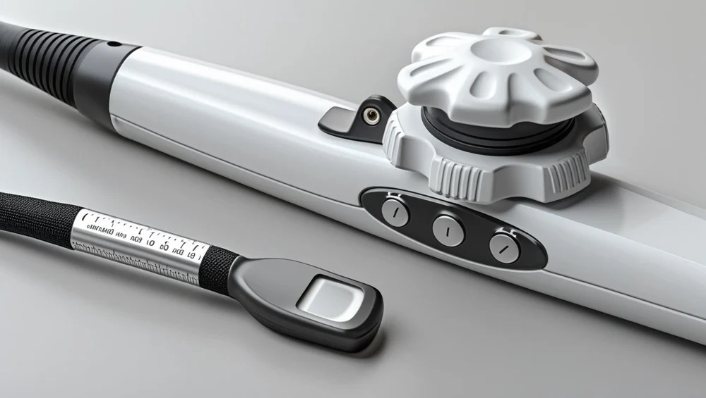
One row of sixty-four elements diced at half a wavelength, mounted on a carrier that a small motor in the tip rotates through a hundred and eighty degrees. The operator holds a button and the array turns; the angle is read from a potentiometer geared thirty to one on the motor side of the train and printed on the screen to the nearest degree. Behind the array is a backing block, and behind that the motor, its gearbox and a rotary seal, because the array turns inside a tip that has to be watertight enough to be immersed in disinfectant.
Also called: Transesophageal Echo, Transoesophageal Echo. Arabic: مسبار تخطيط صدى القلب عبر المريء. Device Lab 12 of 69 in BMEssentia Medical City, 2 configurations.
Overview: the configurations
Single-plane phased array with motor-driven multiplane rotation
One row of sixty-four elements diced at half a wavelength, mounted on a carrier that a small motor in the tip rotates through a hundred and eighty degrees. The operator holds a button and the array turns; the angle is read from a potentiometer geared thirty to one on the motor side of the train and printed on the screen to the nearest degree. Behind the array is a backing block, and behind that the motor, its gearbox and a rotary seal, because the array turns inside a tip that has to be watertight enough to be immersed in disinfectant.
Matrix array with electronically steered imaging plane
A forty-eight by forty-eight grid of two thousand three hundred and four elements at the same half-wavelength pitch, in a tip with no moving part in it at all. The imaging plane is produced by a delay pattern across the grid, so changing the plane angle is arithmetic rather than movement and two planes can be interleaved between frames. Two thousand three hundred coaxial cores will not pass down a ten millimetre shaft, so the first stage of beamforming is a chip immediately behind the array, reducing the channel count to something the shaft can carry -- and dissipating its power in the tip.
How it works: the main parts
What each part does, from the TEE Probe lessons in the 3D Device Lab.
- Mains inlet, isolation and protective earth
- A filtered inlet on the back of the console, an isolation transformer behind it, and an equipotential stud beside it. Unremarkable on any medical electrical device, and on this one it carries a boundary that matters more than usual: the probe goes inside a person and its screen returns here.
- Transmit pulser and the per-channel drive
- A bank of high-voltage switching stages, one per transmit channel, that produce the short pulses the array radiates. It is the component that decides how much power enters the probe, and therefore the component that decides how hot the far end gets.
- Preamplifier, time-gain compensation and digitiser
- A low-noise preamplifier per channel, a gain that rises with time after the transmit pulse, and an analogue-to-digital converter behind it. It is the stage that turns microvolts into numbers, and its position in the system differs between the two configurations in a way that matters enormously.
- Envelope detection, compression and scan conversion
- The stage that turns beamformed radio-frequency data into a picture: it detects the envelope, compresses a very large dynamic range into the small one a display has, and converts the polar or steered geometry of the beams into the rectangular grid of a screen.
- Display, the plane-angle readout and the tip temperature readout
- The screen, and two small numbers on it that are not like the others. One is the imaging plane angle in degrees.
- Console panel, acoustic output control and the freeze
- The control surface: depth, gain, a plane-angle control, a mode selector, an acoustic output control and a freeze key. On this probe two of those controls do something no surface machine asks of them, and one of them is the only way an operator can reduce the heat in the far end.
- Tip thermistor and the automatic freeze
- A small thermistor bonded into the tip assembly close behind the array, two fine wires running the length of the shaft to the connector, and a comparator in the console that freezes the image when the temperature reaches a declared displayed value. It is the only self-measurement in this library that shuts a device down.
- Piezocomposite stack, matching layer and backing block
- The active layer and the two things bonded to its faces: a quarter-wavelength matching layer in front, taking the acoustic impedance of the ceramic down towards that of tissue, and a heavily loaded backing block behind, absorbing what goes the wrong way. It is the source of both the sound and the heat.
Explore it in the Device Lab
- One over four k a, and why the tip cannot grow its way out: Leave everything else alone and change only the apposed fraction of the acoustic face. Read the face equivalent radius, the spreading resistance, and the face temperature at each setting. Then compare the acoustic face with the tip shell.
- A factor of four per degree, and the factor the machine does not hold: Set the tip power and read the face temperature and the thermistor temperature. Then leave both exactly where they are and change only the examination length. Read the accumulated equivalent time before and after.
- A sensor that reads the hottest thing in the tip, and a fault that makes it safer: Read the face temperature and the thermistor temperature side by side at several powers and confirm which is the higher. Then inject the delaminated lens condition and read both again, and read the four resistances while you are there.
- An aperture that turns with the plane, and one that does not: Set the plane angle to zero and read the in-plane aperture and the lateral resolution at a stated range. Then take the plane to forty-five degrees and read them again. Do it on both configurations.
- A resolution of one hundredth of a degree, about the wrong thing: Read the plane encoder resolution referred to the array, then compare it with the step the display shows. Then introduce the lost-motion condition and watch which numbers change.
Common faults and what to check
Most reported device problems (FDA MAUDE)
| Device problem | Reports |
|---|---|
| Poor Quality Image | 1,302 |
| Device Displays Incorrect Message | 325 |
| Break | 256 |
| Device Operates Differently Than Expected | 115 |
| Material Deformation | 113 |
| Leak/Splash | 110 |
Raw counts of adverse event reports for this device type (FDA product code ITX), all years. Not adjusted for the number of units in use, so they show what gets reported, not failure rates. Report text is never copied.
Planned maintenance checks
From the BMEssentia procedure library: every 12 months, about 30 minutes, electrical class I, applied part type BF.
| Check | Pass when |
|---|---|
| Shaft, tip and controls Inspect the full shaft for bite marks and cracks, the tip lens and the steering controls. | No damage. |
| Leakage test Run the probe leakage test (immersed). | Pass per manufacturer. |
| Steering, image and temperature Check flexion in each direction, the image and the tip temperature display. | All work. |
Test instruments: Probe leakage tester; Bite and tip inspection light.
Standards engineers test against
IEC 60601-2-37: ultrasonic diagnostic and monitoring equipment
The particular standard for diagnostic ultrasound.
Recent FDA recalls
| Recall | Product and reason |
|---|---|
| Z-1622-2026 2026-03-24 | Philips Ultrasound, Inc: Philips Mini Multi TEE Ultrasound Transducer To provide clarification and labelling to define the useful life of ultrasound transducers in the field. Root cause: Device Design. |
| Z-1623-2026 2026-03-24 | Philips Ultrasound, Inc: Philips OMNI II TEE Ultrasound Transducer To provide clarification and labelling to define the useful life of ultrasound transducers in the field. Root cause: Device Design. |
| Z-1624-2026 2026-03-24 | Philips Ultrasound, Inc: Philips OMNI III TEE Ultrasound Transducer To provide clarification and labelling to define the useful life of ultrasound transducers in the field. Root cause: Device Design. |
| Z-0038-2026 2025-10-03 | ImaCor Inc.: ClariTEE Miniaturized TEE probe. Model Number: CLT-010. Production assembly error resulting in the potential for reversed articulation, where moving the lever forward caused the probe tip to anteflex rather than retroflex, and vice versa. Root cause: Process control. |
| Z-2066-2025 2025-07-02 | Philips Ultrasound, Inc: Philips X7-2t Transducer. Ultrasound transducer devices were refurbished beyond their useful life. Root cause: Process control. |
From the FDA recall database (openFDA), newest first, imported 2026-10-22. 18 recalls on record for this device type. Recall text is the FDA's public text; each recall links to the official record.
Learn it, see it in 3D, ask about it
- Ask Essentia about the TEE Probe: answers from named sources, with the device open in its 3D Device Lab beside the answer.
- The TEE Probe on the BMEssentia Platform: the Device Library course, 13 sections from physics to maintenance.
- BMEssentia Medical City: Device Lab 12, the TEE Probe fully assembled in 3D, with lab tasks and the simulations.
Previous: Anaesthesia Machine. Next: IVUS. All 69 devices.
Ask about the TEE Probe
Sign in with your BMEssentia account, or create one, and ask anything about this device.
Ask Essentia